Programming with Arduino
Now you have installed and configured the Arduino IDE for your Arduino Uno and WeMos you can get started programming these devices. Before you start using this tutorials we assume that you already have some programming experience. It doesn't matter if it's Java, Python, Javascript or something else.
Hello world!
Every time you start working with a new programming language you try to understand the platform first. The easiest way to accomplish this is to write a message like "Hello world", we are going to do the same with the embedded-boards in your IoT-kit.
Because our embedded-boards have no display (yet) it's hard to make it print a message. That's why instead we are going to make a LED blink. The boards already have an integrated LED, so it's not necessary to connect it yourself.
Arduino
First try to create a blinking LED on your Arduino Uno.
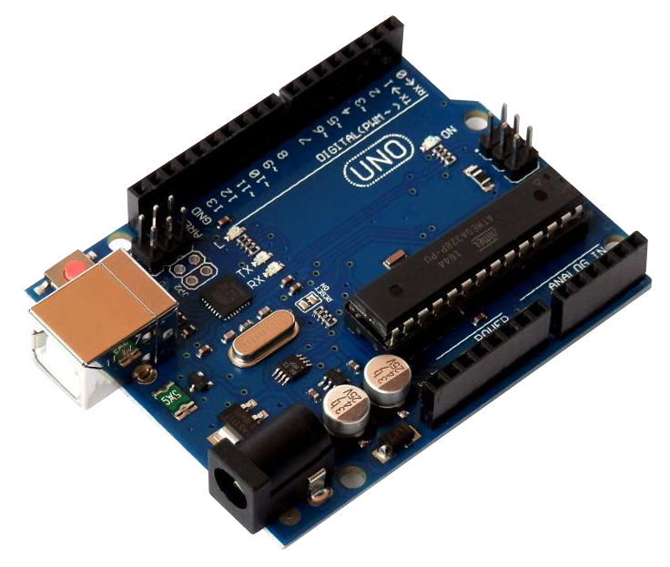
- Connect the board to your computer by using the USB-B cable.
- Open de Arduino IDE and create a new sketch.
- From the menu select the board-type: "tools" > "board" > "Arduino Uno".
- From the menu select the USB-port: "tools" > "Port" > "COMxx" (Windows) or "/dev/ttyxxxxxx" (Mac/Linux).
- Select the example-sketch, from the menu select "File" > "Examples" > "01.Basics" > "blink".
- Now you will get a window showing you example code, this code will make a LED blink.
- Upload the code to your Arduino Uno by pressing the "Upload"-button in the Arduino IDE.

Wemos
After you have blink-'ed your Arduino Uno and soldered the header pins to your Wemos it's time to try to program your Wemos D1 Mini.
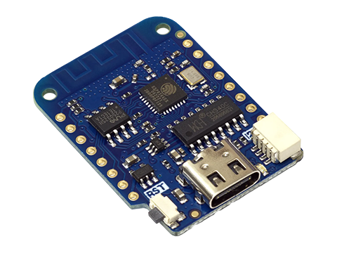
- Connect the board to your computer by using the USB-C cable.
- Open de Arduino IDE and create a new sketch.
- From the menu select the board-type: "tools" > "board" > "LOLIN(WEMOS) D1 R2 & Mini".
- From the menu select the USB-port: "tools" > "Port" > "COMxx" (Windows) or "/dev/ttyxxxxxx" (Mac/Linux).
- Select the example-sketch, from the menu select "File" > "Examples" > "ESP8266" > "Blink".
- Now you will get a window showing you example code, this code will make a LED blink.
- Upload the code to your Wemos by pressing the "Upload"-button in the Arduino IDE.
Arduino in short
You've now soldered your WeMos and tried the example sketch Blink on your Arduino Uno and on your WeMos, both these devices are microcontrollers.
But how does such a device make an LED blink?
Basics
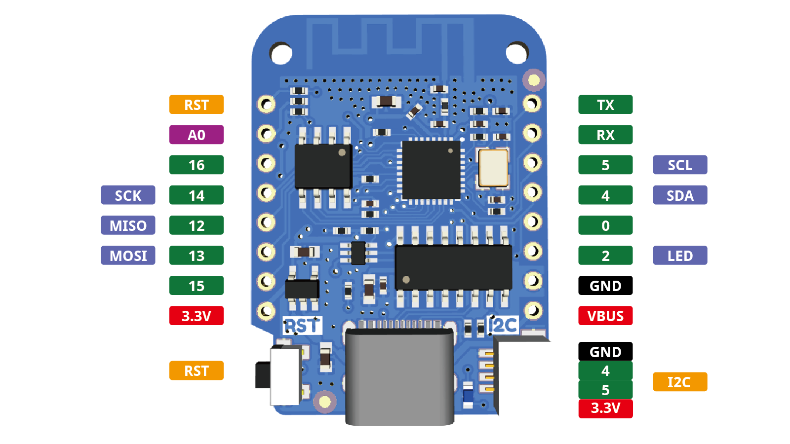
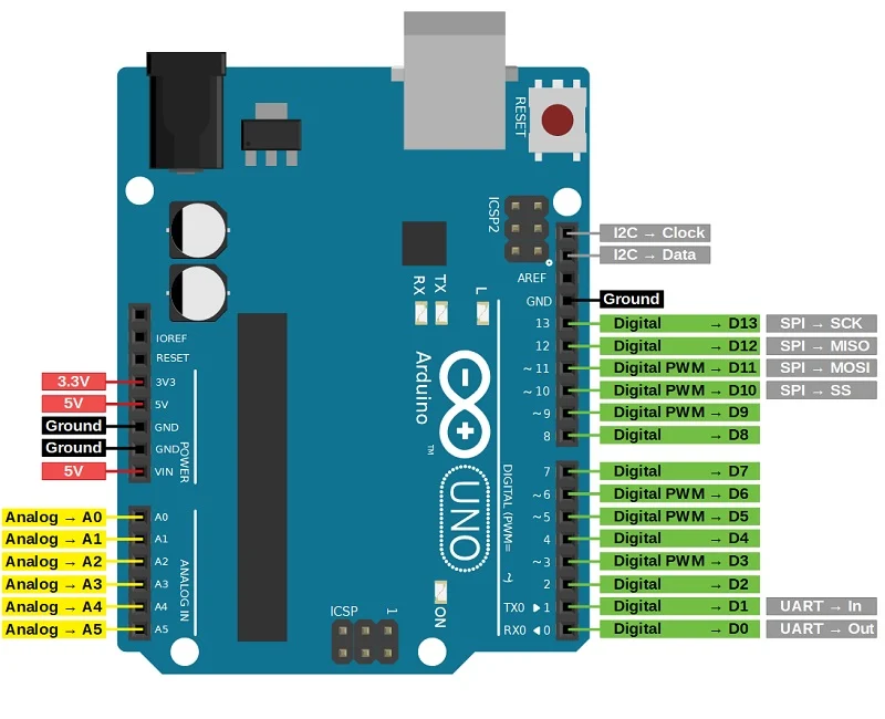
You probably noticed that both devices have all kind of connectors. Some of these serve a specific purpose, like:
- (+)3.3v -> 3.3 volt power supply.
- (+)5v -> 5 volt power supply.
- GND / Ground -> Ground or earth reference point in an electrical circuit.
- UART (out, in, TX, RX) -> For communication between your computer and the device.
Next to the specific purpose pins you also have access to general purpose input/output pins, known as GPIO. These pins can be programmable adjusted. These pins are available in two types:
- Digital
- Analog
And can also be set as an OUTPUT (LEDs, displays, motors, ...) or INPUT (buttons, sensors, ...).
Blinking LED
So you made an LED blink without connecting a LED yourself, the reason for this is because both boards already come with an LED included in the design of the board.
For example when you use the WeMos, if you look at the code of the Blink-sketch you can find the text LED_BUILTIN. This is an constant which will be replaced to D4 by the compiler, because the built in LED of the board is connected to this pin.
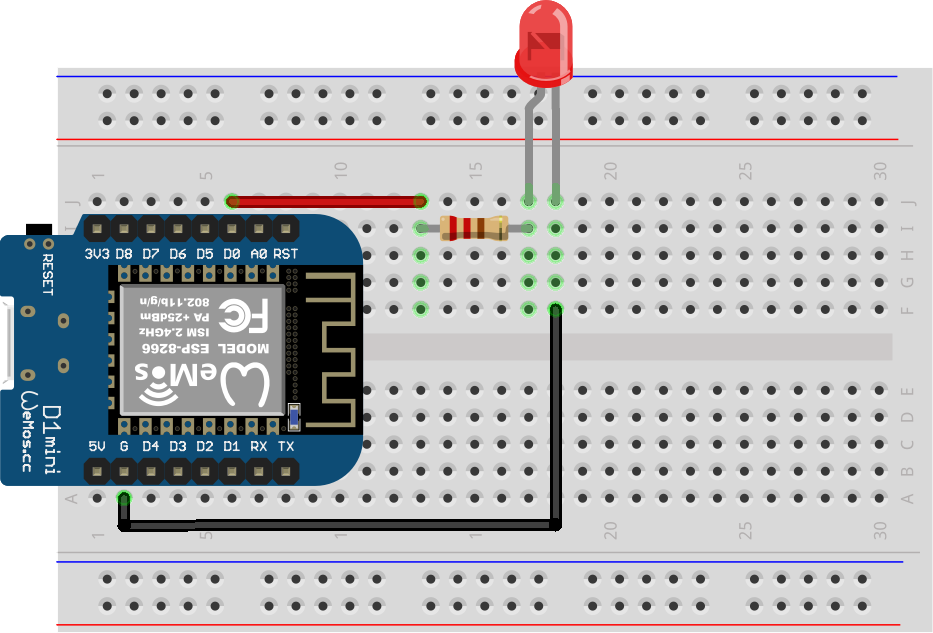
Instead of using the LED on the board you can also connect one yourself, you can choose any GPIO pin if you want to control the LED using code (don't forget to use a resistor!).
In the sketch you can find two functions:
1 2 3 4 5 6 7 | |
When you power the device the setup()-function will be called which initializes and sets the initial values, the loop()-function does precisely what its name suggests, and loops repeatedly.
In this case we have to tell there is something connected to our LED_BUILTIN-pin which is a LED, an output device.
1 | |
Because we only have to set the mode once at start-up you put this line of code inside the setup()-function.
Now to turn the LED on we have to tell the device to set some voltage on the pin. When using the digitalWrite()-function we have to tell which pin and what voltage to use, we have two choices:
- HIGH
- LOW
Depending on the device, HIGH will set the voltage to 3.3v or 5v. LOW will set the voltage to 0V (ground). By using both you can turn something on and/or off.
1 2 | |
When using the WeMos, the loop()-function will be called ~80.000.000 times a second, our human eyes can't see a LED blink that fast so ensure you also add some delays:
1 | |
Buttons
Now we can connect a LED to our microcontroller and know this is an OUTPUT-component it's time to look into an INPUT-component, like a button.
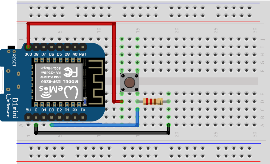
You may have connected buttons before in a subject like physics in high school and were connected in the following way:

This setup could work when using a 230v-light-switch but when working with low voltage you will suffer from disturbances. By including a resistor (pull down resistor) you solve this issue:
Now we can look into the code, this sketch uses D5 to which the button is connected:
1 2 3 4 5 6 7 8 9 10 11 12 13 | |
What stands out in this sketch:
- The pin mode of D5 is set to INPUT.
- Using the digitalRead()-function you can read the value (HIGH or LOW) of the pin.
- Compare the value to HIGH or LOW.
Arduino Tutorials
On the web you can find lots of information and tutorials on how use Arduino. Make sure you get familiar with the tools and programming language. To help you with this we have some websites listed for you:
Testing your program
If you want to test your code with your hardware setup without actually having to use the hardware itself, you can also try out online simulation software as Wokwi.
Using Wokwi has the advantage that you can try out hardware setup without destroying your WeMos.
Note that not all hardware components might be available and it is no garantee that everything will work in the real world.